^Bridge rectifier

^Bridge rectifier

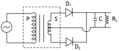
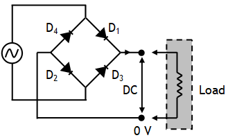
It uses four diodes is shown in figure.

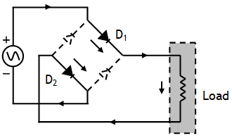
For positive half of input cycle diodes D1 and D2 are forward biased and D3 and D4 are reverse biased. So D1 and D2 conduct but D3 and D4 don’t. Current through RL flows from X to Y.

For negative half of input cycle D3 and D4 are forward biased and D1 & D2 are reverse biased. So in this half cycle D3 and D4 conduct but D1 and D2 do not. Current again flows from X to Y through RL.

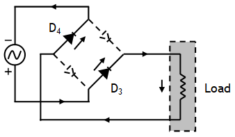
Thus, we see that current through RL always flows in one direction from X to Y.

^Series inductor filter

^Series inductor filter

The resistance offered by an inductor is XL = 2 πfL, it offers low resistance to low frequency currents (i.e. dc) thus only the low frequency currents pass through it & hence pass through RL. High frequency currents are blocked & don’t appear in the output.

^Parallel capacitor filter

^Parallel capacitor filter 

The resistance offered by a capacitor is it offers high resistance to low frequency currents (i.e. dc) or it blocks low frequency currents through it. As a result these low frequency currents can pass through RL only.


^Filter circuits

^Filter circuits

The output obtained from a junction diode rectifier is unidirectional but pulsating. This can be considered as the sum of a dc signal superimposed with many ac signals of different harmonic frequencies. We can obtain dc voltage by filtering out the ac components using two types of simple filter circuits.

^Full wave rectifier

^Full wave rectifier

If during the positive half cycle of the input the end A becomes positive and the end B becomes negative with respect to the center tap C then diode D1 gets towards biased and conducts current D2 is reverse biased and does not conduct. During the negative half cycle the diode D1 gets reverse biased and does not conduct & D2 conducts current. As during both half cycles of input ac the current through load RL flows in the same direction F to C.

^Half wave rectifier

^Half wave rectifier

It gives output only for half cycles of the applied input, thus there is a discontinuity in the current. The same process is repeated again & again for the next positive & negative half cycles. The output voltage is unidirectional but pulsating.


^Principle

^Principle

A diode so offers very low resistance in forward biasing & very high resistance during the reverse biasing. For an ideal diode we assume it offers zero resistance in forward biasing & infinite resistance during the reverse biasing & thus will conduct for only during those cycles in which it is forward biased & doesn’t conduct when reverse biased.

^Rectifier

^Rectifier

A device used to convert AC to DC is called a rectifier. It is based on the unidirectional property of conduction.

^Uses of diode

^Uses of diode

A diode can be used as

  • rectifiers (to convert dc to ac),
  • LED (produce light on forward biasing a diode)
  • solar cells (using solar energy to produce emf)
  • photodiodes (to produce reverse current which can be controlled with intensity of light)
  • Zener diodes (to converting fluctuating dc to constant dc)
  • fast switching OR – gate & AND – gate

^Current in diode

^Current in diode

In forward bias strong diffusion current plus a weak & nearly constant drift current, so that a net current of the order of few mA. & is found to increase with the increase in forward bias voltage.

In reverse bias strong drift current plus a weak & diffusion current so that a net current of the order of few mA flows & is found to be voltage independent upto a critical reverse bias voltage, known as breakdown voltage (Vbr).

error: Content is protected !!
Call 9872662552