^Deflection of EMwaves
^Deflection of EM-waves
EM waves are neutral, thus can’t be deflected by E & B fields.
^Deflection of EM-waves
EM waves are neutral, thus can’t be deflected by E & B fields.
^History of EM waves
In 1865 Maxwell predicted the existence of electromagnetic waves purely from theoretical consideration. He showed that an accelerating charge produce EM waves of wave frequency as that of the oscillating charge.
In 1887, Hertz succeeded in experimentally confirming the existence of em waves. He sued an oscillatory LC circuit for producing these waves he was able to produce and detect e.m. waves of wavelength around 6 m.
In 1885 J.C. Bose succeeded in producing EM wave of much shorter wavelength (5 mm to 25 mm) with the help of a self designed radiator. He was able to transmit EM waves over a distance of about 20 m.
In 1896 Marconi, succeeded in transmitting EM waves across the British Channel in 1899 and across the Atlantic ocean in 1901. His experiments marked the beginning of radio communication.
^Generating EM waves
Maxwell suggested an accelerating charge produces EM waves. An electric charge oscillating harmonically with time produces an oscillating electric field in its neighbourhood & this field in turn produces an oscillating magnetic in the neighbourhood. The process continues because the oscillating electric and magnetic fields act as sources of each other & hence an EM wave originates from the oscillating charge. The frequency of the EM wave is equal to the frequency of oscillation of the charge. The energy carried by the wave comes from the source which makes the charge oscillating. To generate an EM wave of frequency f, we need to set up an ac circuit in which the current oscillates at the frequency f. It is easier to generate low frequency EM waves such as a radio wave than to produce high frequency EM waves. e.g. the generation of yellow light requires an oscillator of frequency 6 x 10¹⁴ Hz, while the modern oscillators have frequency not above 1011 Hz.
^Maxwell law
Just as Faraday’s law tells us that a time-varying magnetic field produces an electric field, the Ampere-Maxwell law predicts that a time-varying electric field produces a current & magnetic field.
This current is called Maxwell displacement current.
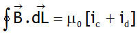
Let ![]() is the rate of change of electric flux of through the area bounded by the closed curve along which the circulation of
is the rate of change of electric flux of through the area bounded by the closed curve along which the circulation of ![]() is calculated, then Maxwell -Ampere law is expressed as
is calculated, then Maxwell -Ampere law is expressed as
![]()
Here 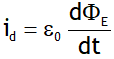 is called the displacement current.
Consider a uncharged parallel-plate capacitor connected to a battery through a switch. On closing the switch the charge on capacitor plates increases, which increases the electric field & electric flux linked with any imaginary loop considered parallel to the area of capacitor plates. This induces a displacement current in the direction of electric field, the magnetic field due to this current is calculated using the AML i.e.

If the capacitor plates has vacuum, then the conduction current will be zero, however due to displacement current the magnetic field at a point on the surface of loop L will be 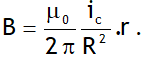
If a loop is situated at r = R, then 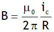
If a loop is situated at r > R, then the loop encloses a displacement current equal to conduction current & the magnetic field becomes 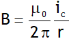 .
.
Also a compass needle place any where around a connecting wires or in the capacitor spacing deflects till the capacitor is undergoing charging or discharging.
^Advantages of ac
1. economical than dc.
2. can be easily transformed from low voltage to high voltage or vice versa using transformers.
3. can be transmitted to distant places with comparatively smaller energy losses.
4. can be controlled using choke coils without having appreciable energy losses.
5. can be converted to dc using rectifiers.
Limitations of ac
6. can’t be used in electrolysis.
7. Shock of 220 V ac is more dangerous than that of 220 V dc.
8. Special wires (a combination of large number of thin wires insulated from each other) are used to carry ac due to skin effect.
^Transformer
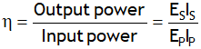
Transformer is an electric device based on of mutual induction used to transfer power from the primary to the secondary by
convert low alternating voltage (at high alternating current) into high alternating voltage (at high alternating current) & vice versa without any transfer of charge. Its efficiency is defined as
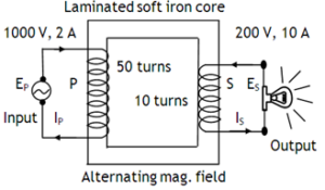
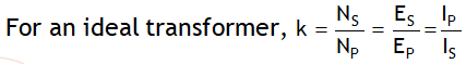

k > 1 for a step up & k < 1 for a step down.
Because of energy losses like Flux loss, Cu- loss,
Fe – loss, Hysteresis loss, Humming noise, the efficiency of a transformer is never 100 %
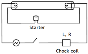
^Choke coil
A coil having large inductance & small resistance connecting it in series with a fluorescent tube in order to control current in it without appreciable power loss.
Application of chock coil A resistor due to larger power dissipation is not used. For a normal inductor consumes power smaller than consumed by a resistor by a factor of 
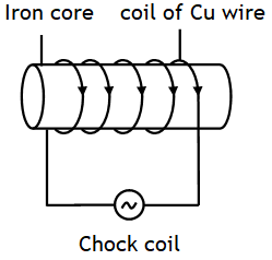
As 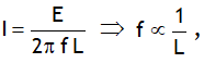 thus for a given emf to reduce low frequency alternating current the choke coils with high inductance i.e. inductors with soft iron cores are used & for reducing high frequency alternating currents the choke coils with low inductance i.e. inductors with air as core are used .
^Motor starter
It is a variable resistor (maximum when the motor is just switched on & its value decreases gradually as the motor picks up the speed) used in the series of the armature to supply the constant current to the motor & thus to protect the motor from burning.
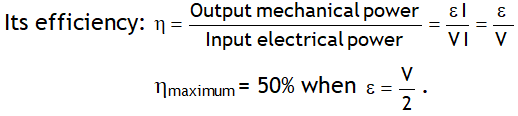
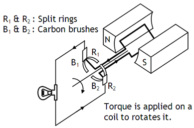
^dc motor
Slip ring arrangement used in ac generator is replaced by split ring arrangement in dc motor. Current flowing in the motor is given by ![]() . It is maximum when the motor is just switched on as then induced emf is zero. This strong current may even burn the coil. As the motor picks up the speed, emf induced in the coil increases & as a result current in it starts decreases.
. It is maximum when the motor is just switched on as then induced emf is zero. This strong current may even burn the coil. As the motor picks up the speed, emf induced in the coil increases & as a result current in it starts decreases.
^LC R parallel circuit or rejecter circuit
Reciprocal of impedance Z is called admittance Y. Current delivered by the supply is I = I1 + I2


If the source oscillates at angular frequency  then imaginary part of Y becomes zero & Y is minimum. This stage is called resonance. Following points are of interest at resonance.
1. The reciprocal of the minimum value of Y is called the parallel or dynamic resistance, it is 
2. Peak current through supply ![]()
3. Peak current through ![]()
4. Q – factor or current magnification i.e. the ratio of the peak current through supply to that through 
5. Used as transmitting circuits.