Posts

^Resolving limit of human eye

^Resolving limit of human eye

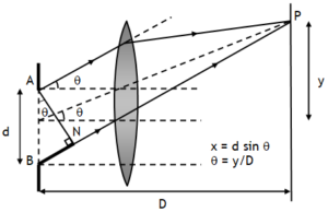
For human eye resolving limit is one  minute (abbreviated as, 1), this means that the human eye can see two point objects separately if they subtend angle more than one minute of arc at the eye. The diameter of the pupil of human eye is about 2 mm. If we use λ= 5000 A0 to see objects, then the smallest angular separation between two distant point objects that the human eye can resolve is

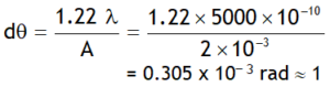
Thus the human eye can see two point objects distinctly if they at the eye an angle equal to one minute of arc. This angle is called the limit of resolution of the eye.

Light rays coming from any object after passing through pupil & eye lens get focused on the retina (screen) in the form of diffraction pattern. We know the maximum intensity of light is diffracted mainly in the central maxima. If the light rays is coming from two objects situated either too close to each other or very far away from eye then their central maxima of their diffraction pattern overlap at the retina, stimulating almost same cells on retina & brain gets one signal & we have perception that we are viewing one object in other words eye fails to resolve (or separate) the two objects if they subtend small angles at eye. e.g. a vehicle with its head lamps ON is approaching us. When the distance of the vehicle from us is large then the angle subtended by the head lamps at the eye is very small, if this is less than one minute then the diffraction pattern of their images at the retina overlap & we have perception of one head lamp. But as the vehicle approaches us the angle subtended by the head lamps at the eye increases, once this angle is more than one minute of arc, diffraction pattern of their images at the retina are formed at different points, exciting retina cells at two different & there by sending two signals to brain & we have perception of two different head lamps now.

Due to the same reason we fail to resolve two nearby stars.

^Resolving power

^Resolving power

The reciprocal of the limit of resolution of an optical instrument is called the resolving power. The resolving power of an optical instrument is its ability to resolve or separate the images of two nearby point objects so that they can be distinctly seen.

^Resolving limit

^Resolving limit

Inability of an optical instrument (eye, microscope, telescope) to resolve the separation of two objects is called its resolving limit or limit of resolution & can be define as the smallest linear or angular separation between two points that can be just resolved i.e. visible distinctly & clearly by it.

^Resolving power of optical instruments

^Resolving power of optical instruments

Suppose a convex lens is used to form the image of an object. Consider a parallel beam of light falling on it. If the lens is well corrected for aberrations, then geometrical optics tells us that the beam will get focused to a point, producing a sharp image point. However, because of diffraction, the beam instead of getting focused to a point gets focused to a spot of finite area in the form of alternate bright & dark concentric circles around a central bright disc as shown in figure. This spot is called the diffraction pattern.

A detailed analysis shows that the radius of the central bright region is approximately given by,

Thus the conclusion is a parallel beam of light incident on a convex lens gets focused to a spot of radius,   
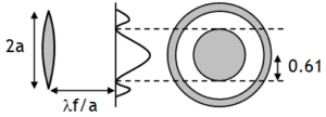
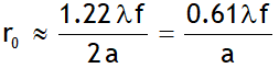
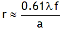
because of diffraction effects.  Where f is the focal length of the lens and 2 a (= d) is the diameter of the circular aperture or the diameter of the lens.

^Resnel’s distance (DF)

^Resnel’s distance (DF)

The distance of the screen from the slit at which the diffraction spread of a beam is equal to the size of the aperture of the slit is called Fresnel’s distance. i.e., when y = d, D = DF, thus  

For a given value of d the quantity  is called the size of Fresnel zone and is denoted by dF.

Geometrical optics or ray optics is based upon the rectilinear propagation of light. If D < DF, then there will not be too much broadening by diffraction i.e., the light will travel along straight lines and the concepts of ray optics will be valid.

^Diffraction spread

^Diffraction spread

From the above discussion it is clear that a parallel beam of light of wavelength λ on passing through an aperture of size d gets diffracted into a beam of angular width,

If a screen is placed at distance D, this beam spreads over a linear width,

If the diffraction spread y is small, only then the concept of ray optics will be valid.

^Intensity of fringes

^Intensity of fringes

Intensity of fringes at point P is

Here I0 is the intensity of central maxima. For nth secondary maxima,

From above points we have the following plot.

Also using the relation of intensity we can say

  • Maximum intensity is central maxima.
  • Most of the light is diffracted between the two first order minima.
  • The intensities of secondary maxima relating to the intensity of central maximum are in ratio,
  • The intensity of the first secondary maximum is just 36 % of that of the central maximum.
  • As the width of a secondary maximum 
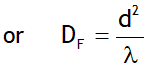
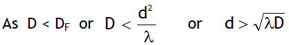
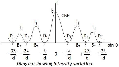
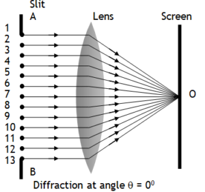
thus as the slit width is increased, the secondary maxima get narrower. If the slit is sufficiently wide, the secondary maxima disappear and only the central maximum is obtained which is the sharp image of the slit and not a diffraction, thus a distinct diffraction pattern is possible only if the slit is very narrow.

^Position of maxima

^Position of maxima

Also it is found that at P for nth maxima

In a similar way the angular position of nth bright fringe is

i.e. angular positions of 1st, 2nd, 3rd maxima are

From above relation we can say that each secondary maxima occupies an angular width of , thus linear width of each secondary maxima is . As the central maxima is a spread between the angular positions to , thus its angular width is i.e. central maxima is twice wider than secondary maxima. Linear width of central maxi. is 

^Position of minima

^Position of minima

Path difference between the wavefronts reaching P from the end of the slits B & A is, x or p = BP – AP = AN Also p = d sinθ =

A detailed mathematical analysis shows that at P for nth minima p = d sinθ = nl, n = ± 1, ± 2, ± 3, _ _ _

For small θ, sinθ » θ

Thus angular position of nth dark fringe is

i.e. angular positions of 1st, 2nd, 3rd minima are

^Diffraction & Huygens’ theory

^Diffraction & Huygens’ theory

Diffraction can be explained using Huygens’ theory. According to this theory all parts of the slit AB will become source of secondary wavelets, which all start in the same phase at that position. The wavefronts from any two corresponding points such as (1, 13), (2, 12), (3, 11) etc. from the two halves of the slit travel identical distances to reach O thus have zero path difference, hence they add constructively to produce a bright fringe at point O, centre called central maxima or central bright fringe.


error: Content is protected !!
Call 9872662552