Sign of thermoelectric power
Sign of S is sign of cold side i.e., potential of cold side. By convention, the sign of S represents the potential of the cold side with respect to the hot side. If electrons diffuse from hot to cold end, then the cold side is negative with respect to the hot side and the Seebeck coefficient is negative. In a p – type semiconductor, on the other hand, holes would diffuse from the hot to the cold end. The cold side would be positive with respect to the hot side which would make S a positive quantity.
The total voltage difference between two points where temp. are T0 and T, from equation (1), is given by 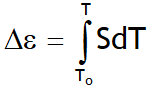 _ _ _ _ (2)
In practice one rarely measures the absolute thermopower of the material of interest. This is due to the fact that electrodes attached to a voltmeter must be placed onto the material in order to measure the thermoelectric voltage.
The temperature gradient then also typically induces a thermoelectric voltage across one leg of the measurement electrodes.
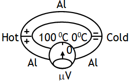
Therefore the measured thermopower includes a contribution from the thermopower of the material of interest and the material of the measurement electrodes. Suppose that we try to measure the voltage difference DV across the aluminium rod (heated at one end and cooled at the other end) by using aluminium connecting wires to a voltmeter as shown.

The same temperature difference, however, now also exists across the aluminium connecting wires and therefore an identical voltage also develops across the connecting wires, opposing that across the aluminium rod.
Consequently no net voltage will be registered by the voltmeter.
It is, however possible to read a net voltage difference, if the connecting wires are of different material, i.e. have a different coefficient than that of aluminium , so that across this material the thermoelectric voltage is different than that across the aluminium rod.
The voltage across each metal element depends upon on its Seebeck coefficient so that the potential difference between the two wires will depend on SA – SB. The emf between the two wires, VAB = DVA – DVB, by virtue of eqn. (2), is then given by
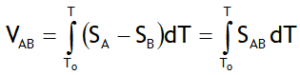
Here SAB is defined as the thermoelectric power for the thermocouple pair A – B.
The Seebeck coefficients are non-linear as a function of temperature, and depend on the conductors’ absolute temperature, material, impurities, imperfections, and structural changes. If the Seebeck coefficients are effectively constant for the measured temperature range, the above formula can be approximated as:
VAB = (SA – SB)·(T – T0)
The thermopower is an important material parameter that determines the efficiency of a thermoelectric material. A larger induced thermoelectric voltage for a given temperature gradient will lead to a larger efficiency. Ideally one would want very large thermopower values since only a small amount of heat is then necessary to create a large voltage. This voltage can then be used to provide electric power.
Typically metals have small thermopowers because most have half-filled bands. Electrons (negative charges) and holes (positive charges) both contribute to the induced thermoelectric voltage thus canceling each other’s contribution to that voltage and making it small. In contrast, semiconductors can be doped (adding impurities) with an excess amount of electrons or holes and thus can have large positive or negative values of the thermopower depending on the charge of the excess carriers.

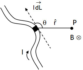
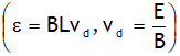 in a current carrying strip of metal or a semiconductor when it is placed in a region of uniform magnetic field acting at right angles to current. It can be used to, calculate drift velocity of charge carriers, number density of charge carriers & nature of charge carriers.