^Young’s double slit experiment
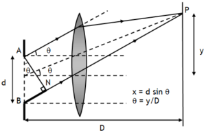
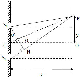
A common experiment to study interference of two light waves is YDSE. In this experiment overlapping of wave fronts of light waves coming from two slits S1 & S2 is studied by placing a screen at some distance from the slits. Let slits are separated by a distance ‘d’ & screen is situated ‘D >>d’ distance away from slits. Wavefronts reaching O from S1 & S2 are of equal path length produce no phase difference & thus we get maximum intensity at O (called central maxima, CM).
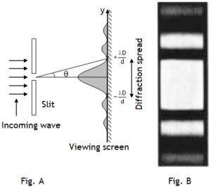
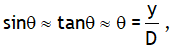
If the overlapping of waves is studied at a point P situated ‘y’ distance above or below the central maxima, then the intensity of the resultant wave depends on the phase difference between the waves S2P & S1P. If point P is situated ‘y’ distance above point ‘O’, then the path S2P is longer than S1P by an amount d sinθ. As here d << D, thus
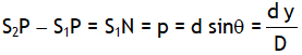
thus path difference (p or Δx or simply x) can be expressed as
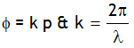
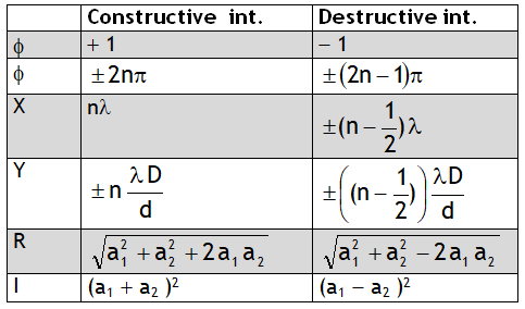
Phase & path difference for a sinusoidal wave are related as
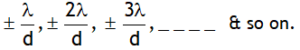
Using above relation for conditions of maximum intensity we can say that maximum intensity is achieved at following positions from central maxima

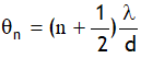
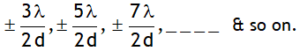
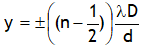
Using above relation for conditions of minimum intensity we can say that minimum intensity is achieved at following positions from central maxima
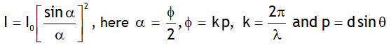
For two waves of equal intensities the intensity of the resultant wave varies as square of the cos of Φ/2 i.e.
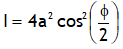
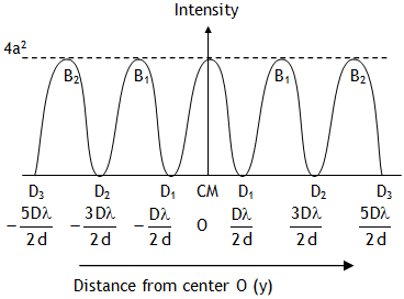
Here 4a2 is the maximum intensity of the resultant wave at central maxima.
Facts
1. Fringe width of any dark or bright fringe is same & is 
2. When interference is studied with white light, each of the seven colours produces its own fringe pattern, having different fringe width & due to overlapping blurred fringes are observed. However central fringe is white, on either side the nearest fringe is blue and farthest fringe is red & then uniform illumination.
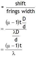
3. If a transparent sheet of thickness ‘t’ & refractive index ‘m’ is introduced in one of paths of interfering waves, the entire fringe pattern displaces towards the side in which the sheet is inserted by a distance  without any change in the fringe.

Also no. of fringes shifted is
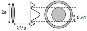
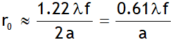
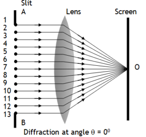
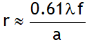 because of diffraction effects. Where f is the focal length of the lens and 2 a (= d) is the diameter of the circular aperture or the diameter of the lens.


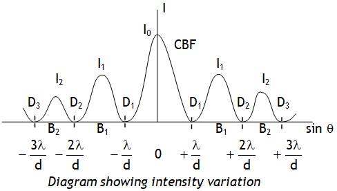
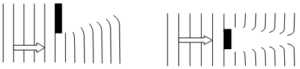
 thus as the slit width is increased, the secondary maxima get narrower. If the slit is sufficiently wide, the secondary maxima disappear and only the central maximum is obtained which is the sharp image of the slit and not a diffraction, thus a distinct diffraction pattern is possible only if the slit is very narrow.