Posts

^Displacement method

^Displacement method

This method is used in the labs to find the focal length of a convex lens.

Consider an object placed between a thin convex lens of focal length ‘f’ & a screen at a distance ‘D’ from the screen.

Using Lens formula for this problem one can write:

To get two distinct images the discriminate > 0.

Thus the essential condition to get two distinct real images on the screen is D > 4 f.

From eqn. (1) the two roots of the quadratic i.e. two different distance of the lens from the object are given by:

From these relations the distance between the two positions of the lens (say ‘x’) can be written as:

The image distance can be written as:

This implies that for the two positions of the lens the image & object distances are interchangeable.

The magnification of the two images can be given by:

^Cutting a lens

^Cutting a lens

(a) If a lens of focal length f is given a longitudinal cut (along aperture) into two equal halves as shown in fig. then the focal length of each half becomes 2f.

(b) If the lens is given a transverse cut (at right angles to aperture) into two halves by a plane parallel to principal axis) then the focal length of each part will remain f.

In this position aperture of prism becomes half, the intensity of the image formed also becomes half (as I ∝ A).

^Combing two convex lenses

^Combing two convex lenses

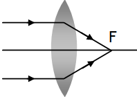
1. Consider a parallel beam of light incident on a combination of two lenses separated by a distance ‘d’ in air or vacuum.

Case (a):

The final beam after refraction from the two lenses becomes parallel if d = f1 + f2

Case (b):

The final beam after refraction from the two lenses converges at a point situated in between both the lenses  if d > f1 + f2 & (d – f1) > f2

Case (c):

The final beam after refraction from the two lenses converges at a point situated outside both the lenses if d < f1

^Combination of lenses

^Combination of lenses

Two or more lenses are combined to

  1. Increase magnification.
  2. Make final image erect.
  3. Reduce certain aberrations.

If two thin lenses of focal lengths f1 and f2 are separated by a distance d then the effective focal length and power of the combination is given by:

1.

2. P = P1 + P2 – d P1 P2

3. m = m1 x  mx  mx – – – – – – – – –

Let us prove the above relations.

* A Zoom lens is based on this result such that f can be varied 0 to ∞ by changing d.

^Image formation by a lens

^Image formation by a lens

(a) A concave lens always form virtual, erect & diminished image irrespective of the position of the object.

(b) With a convex lens following possibilities are there

Position of object
Ray diagram
Image produced
At ∞
At F
Real (inverted)
Extremely Diminished
m < < 1
Beyond C i.e.
Between ∞ and 2 F
Between F & C
Real (inverted)
Diminished
m < 1


At C
At C
Real (inverted)
Same as size of object
m = 1
Between F and C
Beyond C
Real (inverted)
Magnified
Object at F
At ∞
Real (inverted)
Infinite size
m → ∞
Between F and P
Beyond 2 F Virtual (erect)
Magnified
m > 1

^Image formation rules

^Image formation rules

1. A ray passing through optical center of any lens convex or concave at any angle to principal axis goes undeviated.

2. An oblique passing through focus of any lens convex or concave at any angle to principal axis becomes parallel to principal axis after refraction.

3. A ray parallel to principal axis of any lens convex  or concave axis meets or appears to be meeting focus after refraction.


^Curved surface refraction formula

^Curved surface refraction formula

It is a general expression, applicable to both convex & concave surface, for both point & extended object placed in any medium rare or denser, for any type of image formed (real or virtual).

While using this result keep in mind following points:

  1. All distance are measured from the pole P (i.e. the centre of surface at which incident ray strikes.
  2. μ1 → Medium from which incident ray comes.
  3. μ2 → Medium towards which incident ray is sent.

^Porro – prisms

^Porro – prisms

A Porro – prisms is a totally reflected is a right handed isosceles prisms having ∠C = 420, μ = 1.5 and ∠i = 450.  These prisms are used to bend light by 90º or by 180º & to invert images without changing their size. Following are few advantages of TRPs over plane mirrors.

  • Unlike plane mirror, do not require silvering.
  • Almost 100 % reflection is possible in TRP (where as in case of a good plane mirror it is never more than 95%). Hence comparatively brighter image is produced.
  • When used for a long time, the silvered face of mirror deteriorates which reduces the quality of the image. (in TRP there is no such deterioration).


^δ without θ

^δ without θ

Under this condition

This combination is also called Achromatic prism combination.

^θ without δ

without δ

Under this condition

Such a combination is called a direct vision prism. The required condition is

error: Content is protected !!
Call 9872662552