^Diffraction of light
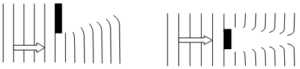
When a wave (light or sound) strikes an obstacle it doesn’t go straight, rather it bends round the obstacle.
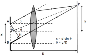
Also when a light wave passing from a narrow slit of width AB = d reaches screen placed at a distance D (>>d) from the slit, (Fig. A) then a bright spot on screen at a point just opposite to slit is expected & all other points on the screen are expected to be dark (called regions of geometrical shadow), but in actual practice light spreads into the region of geometrical shadow and alternate patterns of bright & dark bands (Fig. B) of varying intensity are formed.
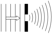
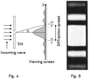
This phenomena of spreading or bending is called diffraction of wave.
a) Diffraction dominates for longer wavelengths.
b) If the wavelength of the wave is smaller than the dimensions of obstacle diffraction is negligible & the wave behaves like a ray & travels along straight line (called, rectilinear propagation).
c) Diffraction in case of radio waves & sound waves is generally observed, because their wave length is not so small & obstacles/ apertures of theses sizes are readily available.
d) Diffraction with light is generally not observed, because light has very small wavelength (»mm) & obstacles of such small size are readily not available.
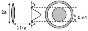
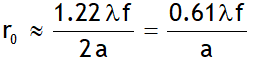
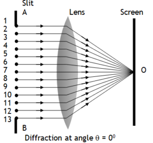
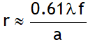 because of diffraction effects. Where f is the focal length of the lens and 2 a (= d) is the diameter of the circular aperture or the diameter of the lens.


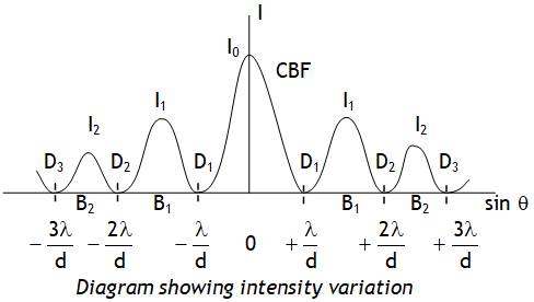
 thus as the slit width is increased, the secondary maxima get narrower. If the slit is sufficiently wide, the secondary maxima disappear and only the central maximum is obtained which is the sharp image of the slit and not a diffraction, thus a distinct diffraction pattern is possible only if the slit is very narrow.