^Advantages of ac

^Advantages of ac

1. economical than dc.

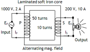
2. can be easily transformed from low voltage to high voltage or vice versa using transformers.

3. can be transmitted to distant places with comparatively smaller energy losses.

4. can be controlled using choke coils without having appreciable energy losses.

5. can be converted to dc using rectifiers.

Limitations of ac

6. can’t be used in electrolysis.

7. Shock of 220 V ac is more dangerous than that of 220 V dc.

8. Special wires (a combination of large number of thin wires insulated from each other) are used to carry ac due to skin effect.

^Transformer

^Transformer

Transformer is an electric device based on of mutual induction used to transfer power from the primary to the secondary by

convert low alternating voltage (at high alternating current) into high alternating voltage (at high alternating current) & vice versa without any transfer of charge. Its efficiency is defined as

k > 1 for a step up & k < 1 for a step down.

Because of energy losses like Flux loss, Cu- loss,

Fe – loss, Hysteresis loss, Humming noise, the efficiency of a transformer is never 100 %

^Choke coil

^Choke coil

A coil having large inductance & small resistance connecting it in series with a fluorescent tube in order to control current in it  without appreciable power loss.

Application of chock coil A resistor due to larger power dissipation is not used. For a normal inductor consumes power smaller than consumed by a resistor by a factor of

As 
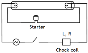
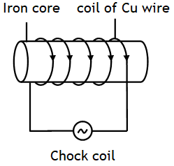
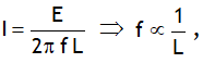
thus for a given emf to reduce low frequency alternating current the choke coils with high inductance i.e. inductors with soft iron cores are used & for reducing high frequency alternating currents the choke coils with low inductance i.e. inductors with air as core are used .

^Motor starter

^Motor starter

It is a variable resistor (maximum when the motor is just switched on & its value decreases gradually as the motor picks up the speed) used in the series of the armature to supply the constant current to the motor & thus to protect the motor from burning.

^dc motor

^dc motor

Slip ring arrangement used in ac generator is replaced by split ring arrangement in dc motor. Current flowing in the motor is given by .  It is maximum when the motor is just switched on as then induced emf is zero. This strong current may even burn the coil. As the motor picks up the speed, emf induced in the coil increases & as a result current in it starts decreases.

^LC R parallel circuit or rejecter circuit

^LC R parallel circuit or rejecter circuit

Reciprocal of impedance Z is called admittance Y. Current delivered by the supply is I = I1 + I2

If the source oscillates at angular frequency  then imaginary part of Y becomes zero & Y is minimum. This stage is called resonance. Following points are of interest at resonance.

1. The reciprocal of the minimum value of Y is called the parallel or dynamic resistance, it is

2. Peak current through supply

3. Peak current through

4. Q – factor or current magnification i.e. the ratio of the peak current through supply to that through

5. Used as transmitting circuits.

^LCR series or acceptor circuit

^LCR series or acceptor circuit

If the generator oscillates at a frequency equal to natural frequency of LC oscillator 
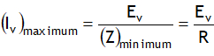
then current in the circuit becomes maximum & the stage is called resonance. Following points are of interest at resonance.

1. XL= XC, Z = min. = R

2.

3. Φ = 0

4. Quality factor or Q factor or voltage multiplication factor is defined as the ratio of voltage across inductor (or capacitor) VL (or VC) to ratio of voltage across a resistor at resonance. i.e.

5. Also

Here ω1 & ω2 are called half power side band frequency.

6. Value of Q describes the sharpness of I – ω curve at resonance.

If band width is low, the quality factor will be high & the I – ω graph will be thin & sharp & vice – versa as shown in the following plots. Higher the value of Q-factor, the narrower & sharper is the I – ω curve at resonance.

The larger the value of Q – factor, the smaller is the value of 2 Δω or the bandwidth and sharper is the resonance.

^Impedance triangle

^Impedance triangle

Impedance triangle is also called ac triangle.

It is obtained by the phase relationship between I & V for various elements of a given circuit & is useful to find X, R, Z, Φ, PF, Iv, Pav & WLC.

Here     X = net reactance of the circuit and R = resistance offered by the pure resistor.

^Power factor

^Power factor

Power factor is defined as, .

Its value lies between 0 & 1. To decrease the power loss in the transmission we have to increase the power factor, we can do this by making Z tend to R, for this we have to include a capacitor in the circuit.

^Wattless current

^Wattless current

The average power consumed by a pure inductor & a pure capacitor is zero while that by a pure resistor is maximum. The current flowing in a pure inductor & a pure capacitor doesn’t dissipate any power. Such a current is called wattless current or idle current. Its amount is Iv sinΦ.

error: Content is protected !!
Call 9872662552