^Impedance
^Impedance
Net resistance offered by the combination of L, C & R to current in an ac ckt. is called impedance (Z).
^Impedance
Net resistance offered by the combination of L, C & R to current in an ac ckt. is called impedance (Z).
^Current in ac circuits
Let E = E0 sin ωt is the sinusoidal source of emf applied to a circuit. Let Φ is the phase difference between current & the emf applied is, then the current flowing through the circuit can be represented by the general relation
I = I0 sin (ωt + Φ), its virtual value of current is 
Current flowing in a circuit depends upon following factors:
(a) input voltage signal
(b) frequency of the input voltage signal
(c) nature of circuit elements in the circuit
(d) combination of circuit elements in the circuit
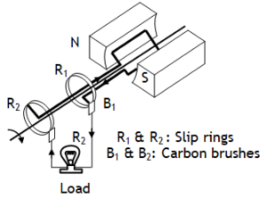
^ac generator
Also called dynamos or electric oscillators or commutators is based on EMI. When a metallic – coil is rotated at a high speed in a strong magnetic field, due to the change in magnetic flux linked with the coil a voltage difference ε = ε0 sin ωt, ε0 = BANω is induced across the two ends of the coil connected to the rings R1 & R2 called Slip rings, which when fed to external load through carbon brushed B1 & B2 can supply current to load.
^Sac (Sinusoidal alternating current)

^LC oscillator or tank circuit
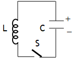
When a charged capacitor is connected to a pure inductor & left for discharging, electromagnetic energy oscillates between capacitor & inductor in due to the sinusoidal variation of charge accordance with the relation 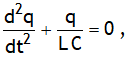 with q = q0 cosωt &
 ![]() .
.
LC oscillator is equivalent to oscillations of a block connected to a spring on a smooth horizontal surface with following analogy
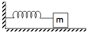

In actual practice the oscillations are damped as every inductor has some resistance.
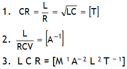
^Also dimensionally:
Example of LR circuit
Let at t = 0, switch S is closed.
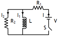
(a) Just on closing switch means t = 0. At this time inductor offers infinite resistance, thus I = 0 and 
(b) A long time after closing switch means at t = ∞. At this time it offers no resistance (as current in inductor attains a maxima), in other words entire current will pass through inductor, hence at t = ∞, I2 = 0 and 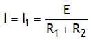
^Current in LR – circuit
An ideal inductor has no ohmic resistance (i.e. R = 0) it has only reactance (i.e. XL ≠ 0). However no inductor is ideal, every inductor can be assumed as series combination of L & R . When such an inductor is connected is connected to a battery (e.g. on throwing switch towards) a current increases exponentially in the outer loop from 0 to become maximum in accordance with the relation ![]()

Due to increase in current voltage across the resistor increases in accordance with the relation ![]()
As the total voltage across the LR combination is always fixed & equal to battery voltage, thus the increase in voltage across the resistor implies a decrease in voltage across the inductor. This is described by the function ![]() .
.
On throwing switch towards B current decreases exponentially in the outer loop from maximum to become 0 in accordance with the relation ![]()
^Eddy currents
Opposing currents produced in the whole volume of a metallic body in the form of closed loops due to the change in magnetic flux linked with a body oppose the change in magnetic flux & can be so strong that the metallic body become red hot.
^Combination of inductors

^Coefficient of coupling (K)
It is defined as, 
(A) The value of K is 0 < K < 1 for loose coupling (i.e. When the axis of two coils are parallel to each other & on different lines )
(B) K = 1 for tight coupling ( i.e. when two coils are wound on each other).
(C) When the axis of two coils are ⊥ to each other & on different lines K = 0 & this case is called zero coupling.
