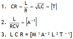
^Also dimensionally:
^Also dimensionally:
Example of LR circuit
Let at t = 0, switch S is closed.
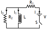
(a) Just on closing switch means t = 0. At this time inductor offers infinite resistance, thus I = 0 and 
(b) A long time after closing switch means at t = ∞. At this time it offers no resistance (as current in inductor attains a maxima), in other words entire current will pass through inductor, hence at t = ∞, I2 = 0 and 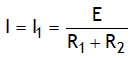


 .
.