^Sac (Sinusoidal alternating current)
^Sac (Sinusoidal alternating current)

^Sac (Sinusoidal alternating current)
^LC oscillator or tank circuit
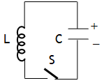
When a charged capacitor is connected to a pure inductor & left for discharging, electromagnetic energy oscillates between capacitor & inductor in due to the sinusoidal variation of charge accordance with the relation 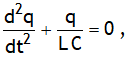 with q = q0 cosωt &
 ![]() .
.
LC oscillator is equivalent to oscillations of a block connected to a spring on a smooth horizontal surface with following analogy
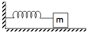

In actual practice the oscillations are damped as every inductor has some resistance.
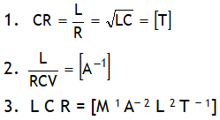
^Also dimensionally:
Example of LR circuit
Let at t = 0, switch S is closed.
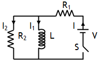
(a) Just on closing switch means t = 0. At this time inductor offers infinite resistance, thus I = 0 and 
(b) A long time after closing switch means at t = ∞. At this time it offers no resistance (as current in inductor attains a maxima), in other words entire current will pass through inductor, hence at t = ∞, I2 = 0 and 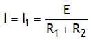
^Current in LR – circuit
An ideal inductor has no ohmic resistance (i.e. R = 0) it has only reactance (i.e. XL ≠ 0). However no inductor is ideal, every inductor can be assumed as series combination of L & R . When such an inductor is connected is connected to a battery (e.g. on throwing switch towards) a current increases exponentially in the outer loop from 0 to become maximum in accordance with the relation ![]()

Due to increase in current voltage across the resistor increases in accordance with the relation ![]()
As the total voltage across the LR combination is always fixed & equal to battery voltage, thus the increase in voltage across the resistor implies a decrease in voltage across the inductor. This is described by the function ![]() .
.
On throwing switch towards B current decreases exponentially in the outer loop from maximum to become 0 in accordance with the relation ![]()
^Eddy currents
Opposing currents produced in the whole volume of a metallic body in the form of closed loops due to the change in magnetic flux linked with a body oppose the change in magnetic flux & can be so strong that the metallic body become red hot.
^Combination of inductors

^Coefficient of coupling (K)
It is defined as, 
(A) The value of K is 0 < K < 1 for loose coupling (i.e. When the axis of two coils are parallel to each other & on different lines )
(B) K = 1 for tight coupling ( i.e. when two coils are wound on each other).
(C) When the axis of two coils are ⊥ to each other & on different lines K = 0 & this case is called zero coupling.

^Mutual induction (M)
1. Property of a coil due to which it suppress the variations in current in it by inducing a back EMF in the neighbouring coil is called mutual induction. It is measured by a quantity called mutual inductance (M), which is defined as,  .
.
2. SI unit of both self & mutual inductance is henry (H).
3. For two long coaxial solenoid wound on same core, ![]()
4. Reciprocity theorem: M12 = M21

^Self induction
1. Property of a coil due to which it suppress the variations in current in it by inducing a back EMF in itself is called self induction. It is measured by a quantity called self inductance (L), which is ![]()
2. For a coil & long solenoid
(a) self inductance, L = A l μm n2
(b) Magnetic energy is, ![]()
(c) Magnetic energy density is, 
3. An inductor (also called a solenoid, or long coil or electromagnet) bent in the form of a coil & made from a thick wire of negligible resisitivity so as to have zero ohmic resistance e. R = 0 is called an ideal inductor or solenoid.
^emf by changing area
Diagram shows a rectangular loop of length L, breadth b, moved towards a region of uniform magnetic field B at a uniform velocity v.
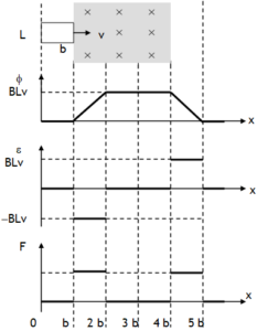
Due to change in magnetic flux with time the emf induced in the loop is, ε = B L v. This causes current ![]() (clockwise) in loop. Due to current magnetic force
(clockwise) in loop. Due to current magnetic force ![]() acts on length. This tends to retard the loop. In order to pull the wire frame with uniform velocity external force
acts on length. This tends to retard the loop. In order to pull the wire frame with uniform velocity external force ![]() is to be applied on the loop. The rate at which the applied force does work to maintain the velocity of the wire frame is
is to be applied on the loop. The rate at which the applied force does work to maintain the velocity of the wire frame is 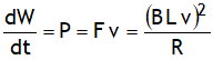 . This work done is actually appearing in the form of electric energy in the loop.