Current mechanism in conductors
In metals about 10 29 m – 3 of free electrons (called average number density ‘n’ ) move randomly (disordered) in all directions (like motion of gas particles) with average thermal speed of about 105 m/s & collide randomly with the metal ions (almost fixed). Between the collision the free electrons travel along straight lines with average relaxation time (t) of about 10 – 14 s, however due to random motion net charge (electrons) crossing any imaginary plane is zero. On applying external potential difference across a metal an electric field is created in it, which exerts force on electron opposite to the direction of electric field & electron apart from thermal motion (disordered) now start drifting in a definite direction (opposite to the direction of electric field) . Using v – t eqn. the drift velocity of free electrons in metals is 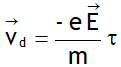 .
.
Average value of drift velocity of free electrons in metals is of the order of few mm /s. Drift velocity per unit applied electric field is called electron mobility (μ) i.e.

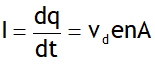
Let ‘n’ be the no. density (i.e. N/V) of free electrons of a metal, then current equation for metal slab of cross sectional area A is

1 A is the flow of 6.25 x 10 18 electrons per second.
 = constant called electrical resistance R, provided there is no change in the physical conditions like temperature, pressure & impurity etc.
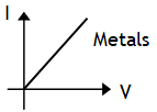

 .
.